The ease of this purchase was a good start. The content of this manual was exactly all I needed to retore my Tandberg 64.
All of the mechanical and electrical information is contained in the manual and the quality of the document makes reading the data easy.
The exerience with the resource has made this my prime source for technical data.
I found this manual to be complete in every detail. Besides the schematic it has a complete set of alignment instructions which are easy to understand. It also includes a complete parts list as well as an explanation of how the power supply and safety shutdown circuits operate. Even a schematic of the tuner is included.
Text excerpt from page 4 (click to view)
CIRCUIT DESCRIPTION
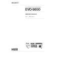
TUNING VOLTAGE GENERATOR
BT BS TU H/L 1 16 BU
VREF Vcc
VCC6
IC500 MSC1169MS-K GND U/V 8 9 VH2 H/L R502 R501 R500 6 11 VH1 TU 7 10 VL1 IN 4 13 VL2 OUT 5 12 U1 BS 2 15
3 14 U2 BT
VREF
GND Figure 1 This circuit generates the DC tuning voltage BT for selecting a channel with a TU pulse being output from IC700. IC500 has 3 circuits for converting pulses to voltages; it selects one of VHF-L, VHF-H, or UHF, and causes the tuning voltage to be output from the OUT terminal (pin 12). Figure 2 and Table 1 show the conditions for selection. IC500 Inputs
VHF -L 11 VHF -H 12
Function U/V L L H H H/L L H L H VHF-L receiving VHF-H receiving UHF receiving UHF receiving