Super Anleitung. Ordentliche Auflösung. Das ganze noch in Deutsch wäre zu schön. Alle Datenblätter sind sauber Kopiert und alle Leitungswege sind sauber ausgeführt
About the service it's very fast and reliable. About the manual the quality is high enough to read even the tiniest details on the wiring diagrams so you can't ask much more than that, let it alone for a manual of a product from 20 years ago. Thank you, very satisfied.
The downloaded quality was as good as the orignial
Text excerpt from page 4 (click to view)
CIRCUIT DESCRIPTION
TUNING VOLTAGE GENERATOR
BT BS TU H/L 1 16 BU
VREF Vcc
VCC6
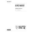
IC500 MSC1169MS-K GND U/V 8 9 VH2 H/L R502 R501 R500 6 11 VH1 TU 7 10 VL1 IN 4 13 VL2 OUT 5 12 U1 BS 2 15
3 14 U2 BT
VREF
GND Figure 1 This circuit generates the DC tuning voltage BT for selecting a channel with a TU pulse being output from IC700. IC500 has 3 circuits for converting pulses to voltages; it selects one of VHF-L, VHF-H, or UHF, and causes the tuning voltage to be output from the OUT terminal (pin 12). Figure 2 and Table 1 show the conditions for selection. IC500 Inputs
VHF -L 11 VHF -H 12
Function U/V L L H H H/L L H L H VHF-L receiving VHF-H receiving UHF receiving UHF receiving