|
|
|
Who's Online
There currently are 5794 guests online. |
|
Categories
|
|
Information
|
|
Featured Product
|
|
|
 |
|
|
There are currently no product reviews.
 ;
Very Good! All the diagram are easy to read, and its complete.
;
This was an excellent source of detailed assembly information on a device which is at least 12 years old. A very lucky find, coupled with great service.
;
Excellent Service Manual and best price on the Internet. This Service Manual covers everything you could ever need including full circuit schematics, component layout diagrams, stripdown procedure and full parts list/breakdown. I needed this to carry out a modification to one of these headunits and this manual covered everything I needed. Fast delivery, processed within a few hours.
 ;
Thought I would never find a copy of the Technics SX-EN2 Service Manual until I found Owner-Manuals.com. Price was very fair and I received the download promptly. While a photocopy, it is quite readable and includes all the pertinent information and diagrams. Thank you Owner-Manuals!
;
I really like this manual and it's reliable.I found and bought easly.thank you.
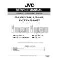
PRECAUTIONS
To prevent damage of the thermal head caused by static electricity when assembling the chassis ass'y into the unit, the following steps must be followed; 1 : Turn the power switch off. 2 : Discharge the capacitor C18(2200µF) on the PCB L271-1. CN301 3 : Connect the FPC of chassis ass'y into a connector CN301 of PCB L271-2. 4 : Assemble the chassis ass'y. 5 : Turn the power switch on.
PCB L271-2
FPC
C18
LSI1
Chassis ass'y
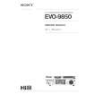
ADJUSTMENT
Adjustment of low battery detection circuit
PCB L271-1
Figure-4
To adjust the threshold voltage of the low battery detection circuit, the following steps must be followed; 1 : Apply 6.2V + 0.1V / -0V to the battery terminals. 2 : Ground check pads CP45 and CP46. 3 : Adjust a pot VR1 so that the voltage between CP1 and CP2 is 0V ± 10 mV.
Multi-meter PCB-L271-1
+
CP2 CP1
VR1 CP46
BATT
-
CP45
+
6.2V (+0.1 / -0 V) Power supply
BATT +
GND
Figure-5 Setting the thermal head rank Set the thermal head rank with pads RNK1 and RNK2 on the PCB L271-1 according to the following conditions when replacing the chassis ass'y or thermal head. The head rank is indicated on FPC as following figure-6. Head rank A : RNK1=ON, Head rank B : RNK1=OFF, Head rank C : RNK1=ON, Head rank D : RNK1=OFF, RNK2=OFF RNK2=OFF RNK2=ON RNK2=ON
XXXXXXB
Head rank = B
XXXXXXB
Figure-6
�4�
Chassis ass'y
|
|
|
> |
|