The schematic is very helpful and the images are very good.The schematic is very helpful and the images are very good.The schematic is very helpful and the images are very good.The schematic is very helpful and the images are very good.The schematic is very helpful and the images are very good.The schematic is very helpful and the images are very good.
The manual for the Sansui P-L75 was not one of the more informative turntable manuals around but for $5 it was helpful enough.
Text excerpt from page 6 (click to view)
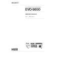
3 CCD (IC802) A charge-coupled device in which charges are introduced when light from a scene is focused on the surface of the device. The image points are accessed sequentially to produce a television-type output signal.
532(H) 508(H)
Effective picture element: 249,936 = 508 (H) x 492 (V) PHIS1~PHIS4: Clock pulse for the storage.
PHI1~PHI4: Clock pulse for the image pickup. PHIH1~PHIH2: Clock pulse for the horizontal shift register. PHIR: CCD analog signal output.
PHIH2
Storage
PHIS4 PHIS1 PHIS2 PHIS3
19 18 17 16
PHIH1
15
492(V)
Horizontal shift register (CCD)
14
4 Camera Signal Processor (IC801)
From CCD
AGC
8bit A/D Converter
D0~D7
D0~D7: Digital signal of the luminance and the color difference B-Y and R-Y signal. CCD IN: CCD analog signal input. VI1~VI4/VS1~VS4: Clock pulse for the CCD control signal.
to CCD
Timing Generator
From/to CPU
Sample Hold Selects a desired signal from the CCD. Timing Genarator Generates the clock pulse for the CCD. 8-bit AD converter Analog signal from the CCD is converted into 8-bit digital signal of the luminance and the color difference B-Y and R-Y signal. .
�4�